



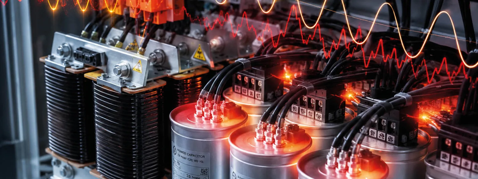
When inverters, UPS, drives, and electronic loads multiply across an installation, power factor correction can no longer be approached with standard logic. In the presence of high harmonic distortion, a capacitor bank designed without the necessary precautions can become a weak point in the system: it overheats, ages faster, suffers overloads, triggers protection devices, and in the worst cases contributes to resonance conditions that worsen power quality instead of improving it.
For this reason, in high-THD environments the question is not simply “apply power factor correction“, but to do so safely. This means starting from correct measurements, choosing the right solution family, and planning detuning reactors, protection devices, ventilation, layout, and maintenance that are consistent with the actual level of harmonic pollution and load behaviour.
THD AND POWER FACTOR CORRECTION: WHY HIGH DISTORTION COMPLICATES EVERYTHING
Traditional power factor correction is designed to correct reactive power and improve the power factor. As long as harmonic content remains low, system behaviour is relatively predictable. When THD increases, however, the picture changes: capacitors no longer “see” only the fundamental component, but also a significant portion of the harmonics present on the network.
This means that the current flowing through them can increase, temperatures can rise, and the bank’s behaviour can become less stable. In environments with a strong presence of non-linear loads, harmonics can damage capacitor banks and reduce overall installation efficiency, making a more careful and technical approach to power factor correction necessary.
THDI VS THDV: JUST ENOUGH TO UNDERSTAND THE RISKS
Good design requires distinguishing between two concepts:
- THDi: current harmonic distortion;
- THDv: voltage harmonic distortion.
In practice, THDi helps to understand how much non-linear loads are “polluting” the current draw. THDv shows how much this distortion is already affecting network voltage at the point in question. The combination of both values matters because a power factor correction bank never operates in isolation: it works within a real network, with a given impedance, a given harmonic spectrum, and a given dynamic behaviour.
TYPICAL FIELD SYMPTOMS
Those working in electrical maintenance often recognise the problem before they have seen the full data. The most common signs are:
- overheating of the bank or switchboard;
- repeated capacitor failures;
- nuisance tripping of protection devices;
- unstable power factor.
These symptoms should not be read as isolated incidents. They often indicate that the power factor correction system is operating in a more severe harmonic environment than originally anticipated.
THE MAIN RISKS: RESONANCE, OVERCURRENTS, AND STRESS ON CAPACITORS
When THD is high, the risks concern not only the effectiveness of power factor correction, but also its operational safety. The critical point is that capacitors, reactors, transformers, and network impedance interact with one another. If this interaction is not considered at the design stage, the bank can become an amplifier of critical conditions.
THE RESONANCE ISSUE
The word “resonance” is often used loosely, but the concept is straightforward: under certain conditions, the combination of network impedance and installed capacitance can amplify specific harmonics. When this happens, the power factor correction system is no longer simply correcting the power factor: it has entered a risky operating zone.
What can trigger it?
- a high proportion of non-linear loads;
- an incorrect bank selection relative to the actual context;
- changes in the installation over time;
- absence of blocking reactors or detuning where required;
- installation at a non-optimal point on the network.
The problem is not merely theoretical: a resonance condition can increase currents and stress on components, accelerating failures and reducing overall reliability.
WHY PROTECTION DEVICES CAN TRIP “FOR NO REASON”
In reality, there is almost always a reason, it simply does not match the classic fault that is looked for first. In a high-THD environment, a protection device may trip because the bank is carrying higher currents than expected, because temperature is rising, because inrush currents or harmonic conditions change rapidly, or because the system is operating at an unstable working point.
When non-linear loads are widespread, an apparent “nuisance trip” is often a signal that the power factor correction design is not perfectly aligned with the actual operating conditions of the installation.
DESIGN CRITERIA FOR ROBUST POWER FACTOR CORRECTION WITH HIGH THD
In the presence of high harmonics, system robustness depends on very concrete choices: architecture, components, thermal management, protection devices, measurement quality, and final commissioning. This is where a well-conceived power factor correction system differs from one that has simply been installed.
DETUNING AND BLOCKING REACTORS: WHEN THEY BECOME ESSENTIAL
When harmonic content is significant, the capacitor bank should not be regarded as an isolated system, but as part of a system that must be protected from interactions with the network. In this context, detuning and blocking reactors serve to shift the system’s operating point away from the most dangerous conditions, reducing the risk of resonance and stress on the capacitors.
In practice, the higher the THD, the more important it becomes to treat these elements not as optional extras, but as a structural part of the project’s safety. Power factor correction solutions include automatic or fixed panels with insertion or blocking reactors, specifically designed to address more demanding installation scenarios.
COMPONENTS AND SWITCHGEAR: WHAT TO ACTUALLY SPECIFY
In a technical specification, the details that prove decisive in service make all the difference. In a high-THD environment, it is important to verify at least:
- suitability of capacitors for the harmonic environment;
- presence and correct sizing of reactors;
- protection devices consistent with the actual behaviour of the bank;
- thermal sizing of the switchboard;
- internal layout that promotes heat dissipation and inspectability;
- degree of protection compatible with the installation environment;
- ease of access for checks, tightening, and maintenance.
An installation with harmonics does not allow the fitting of undersized or catalogue-designed switchgear without appropriate measurements.
WHEN THD IS EXTREME: WHEN IT MAKES SENSE TO CHANGE ARCHITECTURE
There are contexts where a detuned bank is the right choice. There are others where harmonic content, load variability, or continuity and power quality objectives suggest evaluating different architectures, such as dynamic compensation, active filters, or hybrid solutions.
When non-linear loads are very prevalent, active filters can play an important role because they work directly on harmonic cancellation in real time. Within the available product range, for example, solutions dedicated to harmonic reduction in environments with non-linear loads are available, while on the power factor correction side, product families are differentiated by the level of THD they can handle.
INDICATIVE SOLUTION FAMILIES
For contexts with moderate harmonic distortion, lines such as HP10, HP20, HP30, VP10, and VP20 are available, suitable for THD up to 27%.
For environments with high harmonic pollution, lines such as FH20, FH30, FH40, FV25, and FV35 are designed for contexts up to 100% THD.
OPERATIONAL SAFETY AND MAINTENANCE: WHAT TO CHECK OVER TIME
Even a well-designed system can lose effectiveness if it is not monitored over time. In the presence of harmonics, maintenance is not simply about “keeping the switchboard clean,” but about verifying that the bank continues to operate within the intended conditions.
THERMAL CHECK: HOTSPOTS, VENTILATION, CONNECTIONS, DUST
Thermal monitoring is one of the primary health indicators of the system. It is useful to check:
- any localised hotspots;
- ventilation efficiency;
- tightness of connections;
- dust or dirt accumulation;
- environmental conditions that may worsen heat dissipation.
Many problems in high-THD environments manifest first as thermal stress rather than as an outright failure. For this reason, temperature should not be treated as a secondary data point.
PREVENTIVE MAINTENANCE: WHAT TO MEASURE AND WITH WHAT LOGIC
Effective maintenance should include at least:
- monitoring of the power factor over time;
- checking THDi and, where useful, THDv;
- analysis of temperature trends;
- assessment of capacitors condition;
- checking protection devices and recorded trips;
- comparison between the current load profile and the conditions considered at the design stage.
Frequency depends on the context, but the logic is straightforward: the more dynamic the installation and the higher the harmonic content, the more maintenance must be guided by reliable measurements rather than fixed intervals alone.
USE CASE: AUTOMATED MANUFACTURING WITH WIDESPREAD INVERTERS
A typical scenario is a production facility with automated lines, widespread drives, variable loads, and a high requirement for continuity. In these contexts, power factor correction may appear straightforward on paper but becomes more delicate in practice, because the electrical behaviour varies considerably throughout the day and harmonics can be significant.
The presence of inverters, LED lighting, and power electronics is precisely one of the situations where harmonic content can grow to the point of damaging transformers and reducing overall installation efficiency.
TYPICAL PATTERN: VARIABLE LOADS, HARMONICS, AND UNSTABLE POWER FACTOR
The typical picture is as follows:
- lines that change their current draw according to the production cycle;
- non-linear loads introducing harmonics;
- fluctuating power factor;
- protection devices tripping in an apparently random manner;
- components ageing ahead of schedule.
Here, power factor correction must be read as part of a stability strategy, not simply as an administrative correction to avoid penalty charges.
CRITERIA-BASED SOLUTION: HOW TO FIND YOUR BEARINGS
In a case like this, the choice between a detuned bank and a hybrid architecture should not start from price or nominal rating, but from a few key questions:
- is the main problem reactive power, or also harmonic distortion?
- is the THD moderate or very high?
- are the loads stable or highly variable?
- is the objective simply to avoid penalty charges, or also to protect equipment and ensure continuity of service?
When THD is manageable and the primary issue is power factor correction, a well-designed detuned solution may be the correct path. When distortion is very high or highly dynamic, however, it may make more sense to evaluate a solution that integrates or supplements active filtering.
TECHNICAL CHECKLIST: THE MINIMUM DATA TO COLLECT FOR SAFE DESIGN
Before choosing a solution, data are needed. Without reliable measurements, even the best bank risks being over- or undersized relative to the actual problem.
The minimum data to collect are as follows:
KVAR AND POWER FACTOR PROFILE OVER TIME
A single instantaneous value is not enough. It is necessary to understand how reactive power and power factor change across shifts, peaks, start-ups, and different production conditions.
THDI AND HARMONIC SPECTRUM
The total value is useful, but insufficient on its own. The harmonic spectrum helps to identify which components carry the greatest weight and which architecture is most appropriate.
INSTALLATION POINT
Where the power factor correction is installed matters greatly: upstream, downstream, on the main switchboard, or on a dedicated line. The connection point influences system behaviour.
TEMPERATURE AND SWITCHBOARD CONDITIONS
Thermal sizing is not a detail. High temperatures, inadequate ventilation, or harsh environments can significantly shorten component service life.
LOGISTICAL CONSTRAINTS
Available space, accessibility, required IP rating, environmental conditions, maintenance feasibility, and internal layout must all be considered from the outset.
PROJECT OBJECTIVE
Reducing penalty charges, stabilising the power factor, increasing reliability, protecting the bank, reducing the impact of harmonics: the objective must be stated clearly, as it determines the solution.
FAQ
WHEN IS A DETUNED BANK SUFFICIENT?
A detuned bank can be sufficient when the primary issue is power factor correction and the harmonic content, while present, remains within a range that can be managed with appropriate blocking reactors, correct components, and sizing consistent with actual loads.
WHEN SHOULD AN ACTIVE FILTER BE CONSIDERED?
It makes sense to consider one when harmonic distortion is high, dynamic, or significant enough to make a power-factor-correction-only approach insufficient. In these cases, the problem is not just the power factor, but the overall quality of the current and the network.
WHY DO CAPACITORS FAIL IN THE PRESENCE OF HARMONICS?
Because harmonics increase electrical and thermal stress on components. If the bank is not designed for that environment, capacitors may operate outside their optimal conditions, overheat more, and age more rapidly.
HOW CAN RESONANCE BE AVOIDED?
By starting from correct measurements, choosing an architecture suited to the harmonic profile, and incorporating devices such as blocking reactors and detuned configurations where the installation context requires them.
HOW CAN YOU TELL IF THE INSTALLED POWER FACTOR CORRECTION SYSTEM IS UNDER EXCESSIVE STRESS?
The most common signs are high temperature, abnormal protection trips, premature capacitor degradation, unstable power factor, and worsening behaviour as loads change. These are all indicators to be verified through structured measurements and checks.
APPLYING POWER FACTOR CORRECTION CORRECTLY WHEN THD IS HIGH MEANS DESIGNING BEFORE INSTALLING
In the presence of high harmonics, power factor correction is not an accessory component to be added at the end of an installation. It is a sensitive part of the electrical system and must be designed according to criteria consistent with the actual operating context.
This means starting from measurements, reading THD correctly, assessing the risk of resonance, selecting appropriate components and protection devices, checking thermal behaviour, and planning a long-term monitoring programme. Only then does power factor correction cease to be a weak point and become a genuine tool for efficiency, stability, and reliability.


