



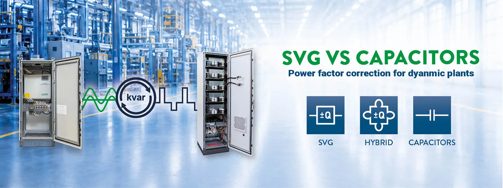
In modern industrial installations, the question is no longer “do I need power factor correction?” but how to apply it effectively without chasing a load that changes continuously. In the presence of drives, rapid work cycles, impulsive loads, or automated lines, the power factor can fluctuate significantly over very short periods. Traditional stepped power factor correction can lag behind these variations, with frequent switching and correction that is not always precise.
The SVG (Static Var Generator) is designed for exactly this: it is an electronic power factor correction system that compensates reactive power with continuous control (not in steps) and very fast response times, bringing stability and precision to contexts where traditional power factor correction may not be adequate.
SVG IN BRIEF
- What it is: a device based on power electronics (inverter) that generates or absorbs reactive power to keep the power factor stable.
- What it does: reduces circulating reactive power, stabilises the power factor, and improves the electrical efficiency of the installation.
- When it makes sense: when a stepped capacitor bank struggles to follow rapid variations, or when finer (including bidirectional) and faster compensation is required.
WHY REACTIVE POWER IS AN OPERATIONAL ISSUE – BEFORE IT BECOMES AN ECONOMIC ONE
It is worth clarifying something upfront: reactive power is not just a line item on an electricity bill. Even if the apparently primary objective is to avoid penalty charges, reactive power has very concrete effects at the installation level.
WHAT CHANGES IN THE INSTALLATION WHEN THE POWER FACTOR IS LOW OR UNSTABLE
When the power factor deteriorates, for the same kW consumed, the current increases: this means that cables, transformers, and busbars work harder relative to the useful energy produced.
In practice, this can lead to:
- greater losses and heating (Joule effect);
- reduced available capacity on transformers and lines (less headroom for new loads);
- greater voltage drops and less stable operating conditions;
- and, depending on applicable tariff rules and consumption profile, additional costs related to reactive power.
This is why a correctly sized power factor correction project is not just about compensating reactive power, but about choosing an architecture and technology consistent with load dynamics and network quality.
TRADITIONAL CAPACITOR-BASED POWER FACTOR CORRECTION: HOW IT WORKS AND WHEN IT IS SUFFICIENT
Before discussing SVG, it is useful to consider the most common reference point: capacitor-based power factor correction.
WHAT “STEPPED” POWER FACTOR CORRECTION IS AND WHY IT REMAINS THE MOST WIDESPREAD CHOICE
Traditional power factor correction uses banks of capacitors divided into steps. A controller measures voltage and current and inserts or removes steps to keep the power factor close to the target. It is a widely used solution because:
- the technology is straightforward;
- it is cost-effective in €/kvar;
- it is highly effective when the load is relatively stable.
WHEN TRADITIONAL POWER FACTOR CORRECTION IS THE RIGHT CHOICE
A stepped capacitor bank is often ideal when:
- the load profile is stable or changes slowly;
- there are no rapid fluctuations in the power factor;
- the harmonic environment is manageable (for example, with dedicated measures where necessary).
TYPICAL LIMITATIONS: WHERE PROBLEMS BEGIN
When load variations are very fast, stepped power factor correction can:
- switch frequently (stress, wear, greater probability of transient conditions);
- be imprecise during phases of rapid variation (over/under-compensation);
- require greater attention in the presence of harmonics, because capacitors can become sensitive to resonance conditions if the system is not properly designed.
WHAT AN SVG (STATIC VAR GENERATOR) IS AND WHAT MAKES IT DIFFERENT
This is where the technological difference comes in: an SVG does not use capacitors but compensates via power electronics (inverter).
CONTINUOUS CONTROL AND BIDIRECTIONAL COMPENSATION (CAPACITIVE AND INDUCTIVE)
An SVG is a system that can modulate compensation continuously and, crucially, work in both capacitive and inductive modes. This is important because in dynamic installations it can be useful not only to add capacitive reactive power, but also to avoid overcompensation under certain operating conditions.
HOW IT WORKS
An effective way to understand it is to think of it as a reactive current controller:
- it measures voltage and current in real time at the CT installation point;
- it separates the reactive component from the active component;
- it calculates how much compensation is needed to reach the setpoint (e.g. power factor 0.99);
- it injects a compensation current via inverter (IGBT) and coupling reactors, modulating it continuously.
The practical result is correction that is far more precise and faster than a stepped logic.
RESPONSE TIMES: WHY THEY REALLY MATTER
Fast response times (typically milliseconds) are needed when the power factor changes rapidly during the process and when real-time compensation is required.
SVG VS STEPPED POWER FACTOR CORRECTION: PRACTICAL DIFFERENCES
| Aspect | Traditional (capacitors) | SVG |
| Compensation logic | Stepped | Continuous (modulated) |
| Dynamic performance on variable loads | Good if load changes slowly | Well suited to rapid variations |
| Bidirectional reactive power | Typically no | Yes (capacitive/inductive) |
| Sensitivity to challenging conditions | Requires careful design (detuning/filters if necessary) | Generally more flexible; filtering only if specifically required |
| Complexity and cost | Simpler and lower cost | More complex, higher cost |
| Typical scenarios | Stable loads | Rapid/impulsive loads, tight setpoints |
WHEN IT GENUINELY MAKES SENSE TO CHOOSE AN SVG (TYPICAL CASES)
The aim of this article is to provide clear technical criteria. If an experienced reader recognises their installation in one of these profiles, SVG deserves serious consideration.
IMPULSIVE LOADS AND RAPID CYCLES
Typical examples are loads with marked variations over short periods (intermittent processes, repeated operations, highly dynamic machining cycles). In these contexts, the SVG’s ability to compensate rapidly reduces power factor fluctuations and stabilises the installation.
CHALLENGING INSTALLATIONS AND THE NEED FOR FINE REGULATION
When conditions are more complex (non-linearities, highly variable profiles, tighter setpoint requirements), an SVG is often preferable because it works continuously and with greater precision than a stepped solution.
THE HYBRID SYSTEM (CAPACITORS + SVG): OFTEN THE BEST SOLUTION
A key point is that there is not always one solution that is definitively better than the other: a hybrid solution is often the most sensible choice:
- a capacitor bank for the base kvar requirement;
- an SVG for fine regulation.
This approach optimises both cost and performance: you pay for the electronics where they are truly needed, without oversizing.
SVG AND HARMONICS: WHAT NEEDS CLARIFYING
A common mistake is assuming that an SVG also resolves harmonic problems in the installation. This is not always the case: an SVG is designed for reactive power compensation.
SVG ≠ ACTIVE FILTER (UNLESS IT IS A COMBINED VERSION)
There are SVG solutions that integrate filtering functions up to a certain level of harmonics. Therefore:
- if the primary issue is dynamic reactive power, an SVG is the right choice;
- if harmonic distortion is also a concern, the architecture needs to be assessed (dedicated filters or combined versions).
HOW TO CHOOSE AND SIZE
Technical content should deliver real value: not formulas, but data to analyse and criteria to apply.
MINIMUM DATA TO COLLECT BEFORE DECIDING ON THE TECHNOLOGY
Before discussing ratings, a coherent set of measurements is needed:
- kW and kvar profile across days and shifts;
- power factor trend and target;
- evidence of rapid variations and transients;
- distortion indicators (at least THD) and network conditions;
- installation configuration (substation, transformers, switchboards, distribution).
SELECTION CRITERIA
- Choose traditional if the load and network are stable: maximum cost/kvar ratio.
- Choose SVG if rapid variations need to be tracked, with fine control and the possibility of bidirectional compensation.
- Choose a hybrid system if you want to optimise budget and performance: cost-effective base capacity plus dynamic control where needed.
SIZING AND MARGINS: WHAT TO AVOID
Two typical mistakes:
- sizing based on the average of measurements and then finding that peaks remain unaddressed;
- oversizing for safety margins and paying for more electronics than necessary (when a hybrid would have been the better solution).
For this reason, in a technical context, measurement of the real load profile is the foundation of the selection process.
FAQ
DOES AN SVG ELIMINATE HARMONICS?
Not necessarily. An SVG compensates reactive power; harmonic filtering is a separate function, present only in dedicated or combined solutions.
CAN AN SVG COEXIST WITH A TRADITIONAL POWER FACTOR CORRECTION SYSTEM?
Yes, and it is often the most rational choice: capacitors for the base load and SVG for dynamics and transients.
WHEN IS INVESTING IN AN SVG “TOO MUCH”?
When the load profile is stable and a well-designed stepped bank (with any necessary measures) already meets the targets without instability or critical switching.


