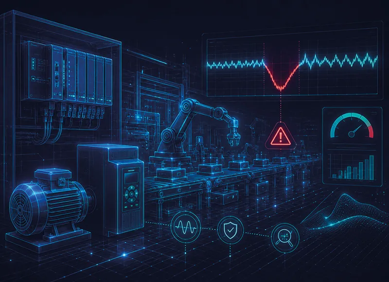



Power Quality is the quality of the electrical supply feeding your processes: stable voltage, correct frequency, controlled distortion, operational continuity. In theory it’s obvious, in practice, a weak grid, a load mix rich in inverters/LEDs, or an external event is enough to trigger voltage sags, micro-interruptions and harmonics.
You don’t “see” the signal, but you feel it: PLC resets, drive trips, rejects downstream of high-speed lines, transformers running hotter than they should, penalties on cosφ. The point isn’t if it happens, but how often and how much it costs.
This page helps you: recognise disturbances from symptoms, estimate their economic impact, and build, without one-size-fits-all fixes, a PQ architecture based on measurements, analysis and targeted interventions.
WHERE ISSUES START (AND HOW THEY SHOW UP)
SAG AND MICRO-INTERRUPTIONS: MILLISECONDS THAT STOP MULTI-MILLION LINES
Sag events are rapid voltage dips; micro-interruptions are very brief losses of supply. In automated environments, just a few milliseconds can put PLCs and drives into fault. The warning sign is often indirect: slow restarts, sudden reprogramming, error counters that reset after a “glitch”. If “nothing happened” on the shop floor but production stopped, a fast event is a likely cause.
HARMONICS: THE PRICE OF NON-LINEAR LOADS
Inverters, LEDs, switching power supplies and efficient drives introduce harmonics. The effect isn’t just theoretical: rising THD, higher temperatures in transformers/switchboards/capacitors, “nervier” protections, lower efficiency. Often the solution isn’t replacing loads but filtering the pollution at its source and preventing resonances.
UNSTABLE VOLTAGE: THE WEAR-AND-TEAR ON MODERN ELECTRONICS
A “high” or unstable grid voltage accelerates ageing of equipment and multiplies rejects. Here, a voltage stabiliser prevents slow/medium fluctuations from turning into quality defects or “mysterious” downtime.
WHAT IT COSTS TO IGNORE POWER QUALITY (A CLEAR, DEFENSIBLE MODEL)
To make it concrete, think like this:
- Line downtime = number of events/years × average duration (min) × cost per downtime minute (including lost output × margin + labour + energy).
- Rejects/rework = rejected parts × unit cost.
- Penalties = cosφ charges + extra consumption due to overvoltage and harmonics.
From this you define:
Annual PQ cost = Downtime + Rejects + Penalties.
Measured on an initial baseline and compared post-intervention, this becomes the basis both for payback and for TCO.
- If the project includes solutions for fast events, add avoided downtime.
- If it introduces filtering / power factor correction, account for reduced losses and penalties eliminated.
That’s how investment becomes a reasoned industrial decision, not an act of faith.
WHICH SOLUTION WHEN (WITHOUT OVER- OR UNDER-SIZING)
VOLTAGE STABILISERS: WHEN GRID VOLTAGE IS UNSTABLE
If the issue is slow/medium fluctuations, voltage stabilisers keep voltage within tight tolerances.
- Electromechanical (Orion/Orion Plus/Sirius range): ideal for high power and “robust but irregular” grids. Mechanical resilience and very wide kVA coverage.
- Static (Aquarius/Odyssey range): very fast response and no moving parts; perfect where regulation speed is critical (healthcare, data centres, sensitive electronics).
A sign you need a stabiliser: product quality that fluctuates by time/shift, “temperamental” electronics, components overheating even without obvious sag events.
OXYGEN & OXYGEN ZERO: WHEN YOU NEED MILLISECOND REFLEXES
If you see sporadic resets or drive trips with no clear cause, the enemy is fast events.
- Oxygen compensates voltage sags in <3 ms and can ride through the event for tens of seconds.
- Oxygen Zero handles micro-interruptions using supercapacitors with a <5 ms
They are often installed to protect the feeders powering PLCs and automatic lines. Where energy savings are also required, they work in tandem with a voltage stabiliser/optimiser: production doesn’t stop and the supply stays at the point of maximum efficiency.
ACTIVE FILTERS: HARMONICS UNDER CONTROL
With high THD, the right choice is the active filter: it measures in real time and injects an opposite current to “cancel” harmonics. Benefits: dynamic response, effective with changing loads, less heat in transformers/switchboards, fewer nuisance trips of protection.
POWER FACTOR CORRECTION: NO PENALTIES, MORE GRID CAPACITY
A correct cosφ frees active power and cuts penalties. On clean networks, HP ranges are enough; where harmonic pollution is high, FH ranges with detuning reactors are needed to avoid resonances and protect capacitors. Rule of thumb: measure THD before selecting components.
OPERATIONAL SUMMARY
- Slow/medium variations -> Stabiliser
- Fast events (ms) -> Oxygen / Oxygen Zero compensator
- High THD -> Active filter
- Low cosφ -> Power factor correction
Many plants need a combination for stable long-term results.
EXAMPLES AND RESULTS: WHAT TO EXPECT
Projects on energy-intensive plants show short ROI when you capture the real costs: downtime, rejections and penalties.
A typical case: stabiliser on an unstable grid -> fewer defects and less stress on electronics; paired with Oxygen on sensitive lines -> avoided downtime; completed with active filter and power factor correction -> a cooler network and a “cleaner” bill. All cloud-monitored, so the before/after isn’t a promise, it’s a chart.
HOW TO SET UP A PQ PROJECT IN 30 DAYS (A REPEATABLE METHOD)
- Kick-off & data collection: single line diagram, load profiles, fault/downtime history, penalties and maintenance notes.
- Field measurements: logs on to critical nodes (substation, MCC, lines): voltage, THD, fast events. If possible, sync with PLC/SCADA logs.
- Analysis & simulation: correlate disturbances ↔ downtime/rejects; intervention scenarios with benefit estimates (kWh, avoided stops, penalties).
- PoC on a critical line: real-life demonstration over a window long enough to capture the phenomena.
- Sizing & design: choose between stabilisers, compensators, active filters, power factor correction systems; define footprint, ventilation, bypass, selectivity.
- Rollout & monitoring: cloud telemetry (trends, alarms on temperature/THD/unbalance) and a preventive maintenance plan to keep results stable.
FAQ
STABILISER OR UPS?
They do different jobs. A stabiliser continuously corrects voltage; a UPS provides autonomy when the supply is absent. In continuous production with loads sensitive to fluctuations, the stabiliser is often the first line; for fast events on process lines, consider Oxygen/Zero.
HOW DO I TELL HARMONICS FROM PHASE UNBALANCE?
Measure THD and neutral currents: high THD with non-linear loads = active filter; strong differences between phases – often with an irregular supply = check load distribution and consider stabilisation.
WHAT’S A REALISTIC RETURN?
It depends on the mix of issues and operating hours. Where short stoppages and unstable voltage coexist, stabilisation + compensation often delivers a fast payback; active filter + power factor correction consolidates the result on both the bill and reliability.
SPACE AND SAFETY: HOW “BULKY” ARE OXYGEN/ZERO?
It varies with kVA. During design you define footprint, ventilation, bypass and selectivity with existing protections. Rule: design “in the substation”, not “from a catalogue”.
AND WITH PV AND BESS?
Compatible: an isolation transformer is often included for safety and voltage matching; upstream, the correct order is filtering -> power factor correction -> stabilisation, with compensation on sensitive lines.
WHY ORTEA (BEYOND THE PRODUCT)
Because it treats Power Quality as a system: measure, design, deliver and monitor.
The breadth of the offer (static/electromechanical stabilisers, sag and micro-interruption compensators Oxygen/Zero, active filters, power factor correction, transformers) lets you combine solutions instead of forcing a single technology. Telemetry and maintenance services close the loop: measurable, repeatable results you can defend in any boardroom.